1. Introduction ( Thermal power Plants)
The use of Thermal Power Plants for electricity generation is quite old. Even after the discovery of many other means of generating electricity, the utility of Thermal Power Plants still exists. The main reason for this is that the working substance, i.e., steam, is generated from water, which is abundantly available in nature. The main fuel for these plants is coal, which is also available in sufficient quantities.
The Rankine cycle : The Rankine cycle is a thermodynamic cycle used in Thermal Power Plants to convert heat energy into mechanical energy. It consists of four stages
1. Isentropic Compression: Water is pumped into a boiler, increasing its pressure.
2. Constant Pressure Heat Addition: High-pressure water enters the boiler, where it absorbs heat from burning fuel, becoming superheated steam.
3. Isentropic Expansion: Superheated steam expands through a turbine, generating mechanical energy.
4. Constant Pressure Heat Rejection: Exhaust steam enters a condenser, where it releases heat and condenses back into water.
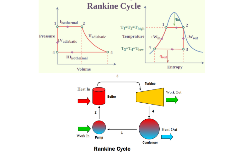
The Rankine cycle operates between two temperature levels:
1) High temperature: Boiler (around 500°C)
2) Low temperature: Condenser (around 30°C)
Efficiency improvements can be achieved through:
1 Superheating
2 Reheating
3 Regenerative feedwater heating
The Rankine cycle is widely used in Thermal Power Plants due to its:
1 High efficiency
2 Reliability
3 Flexibility
The heat-to-electricity conversion process in Thermal Power Plants involves the transformation of thermal energy into electrical energy. The process can be divided into four stages:
1. Heat generation: Fuel combustion produces heat, which is transferred to a working fluid (water or gas).
2. Steam generation: The heat is used to produce high-pressure steam, driving a turbine.
3. Mechanical energy conversion: The turbine converts the thermal energy into mechanical energy.
4. Electrical energy generation: The mechanical energy drives a generator, producing electrical energy through electromagnetic induction.
The efficiency of this process is limited by the Carnot cycle, with an average efficiency of 33-40%.
Thermal power plants generate electricity by converting thermal energy into electrical energy. The process involves:
1. Fuel combustion: Burning fossil fuels (coal, natural gas, or oil) to produce heat.
2. Steam generation: Heating water to produce high-pressure steam.
3. Turbine rotation: Directing steam to turbines, causing them to rotate.
4. Generator activation: Connecting turbines to generators, producing electrical energy.
5. Transmission: Sending electricity to the power grid for distribution.
Thermal power plants can be classified into:
1. Coal-fired power plants –
a)Lignite( lowest carbon content of 25–35% )
b)Peat( low carbon content of 30–40%)
c)Bitumen(second highest 60-80%)
d)Anthracite ( highest carbon 86-97%)
2. Natural gas power plants – Natural gas is primarily made up of methane (CH4)
3. Oil-fired power plants – Heavy fuel oil, Distillate oil, and Crude oil
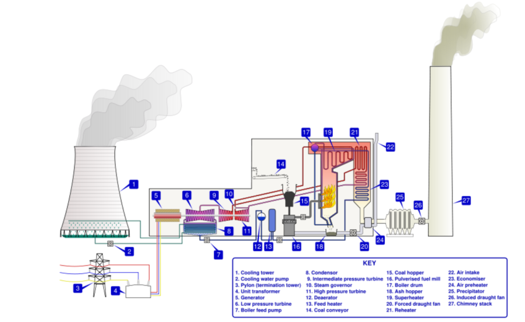
Main Elements of Thermal power plant:
1) Main parts
- Boiler
- Prime mover steam engine or steam turbine
- Condenser
- Electric generator and turbo alternator
2) Auxiliary devices
- Fuel handling
- Fuel combustion
- Ash disposal
- Dust removing
- Cooling water
3) Accessories
- Feed water heaters
- Economizers
- Superheaters
- Air preheaters
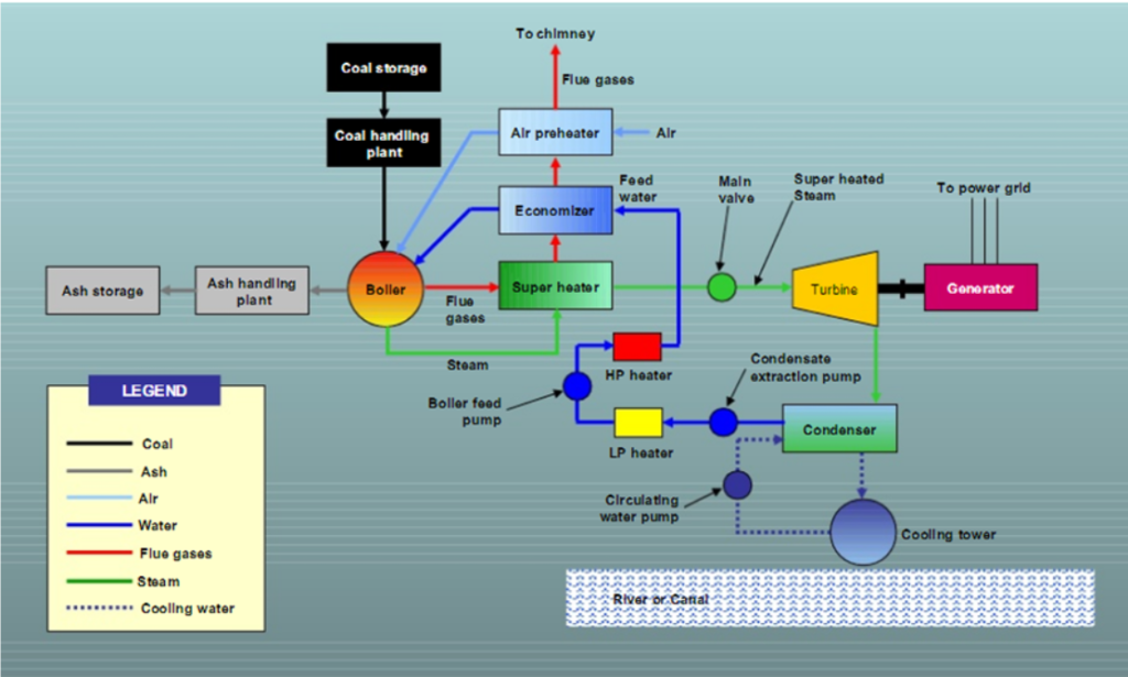
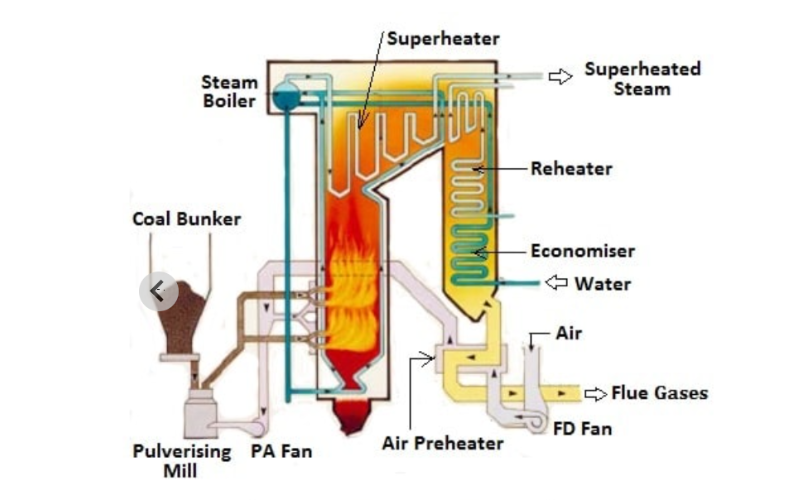
Boilers in thermal power plants:
Thermal Power Plants a boiler is an enclosed pressure vessel where water is heated to produce steam.
Its primary purpose is to transfer heat from the fuel (combustion process) to the water, resulting in high-pressure steam. Fuel (usually coal) is burned in a furnace, generating hot gases. These hot gases come into contact with water in the boiler vessel, transferring their heat energy to the water. The heated water produces steam, which is then piped to the turbine in the Thermal Power Plants.
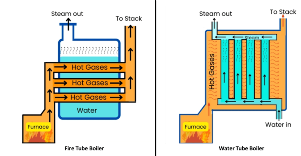
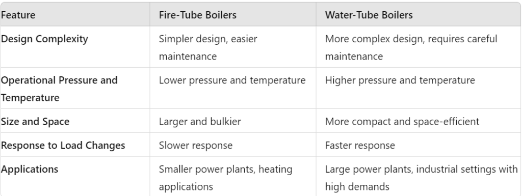
Types of Boilers in Thermal Power Plants:
- Fire Tube Boilers: Water circulates through tubes surrounded by hot gases. Commonly used in smaller Thermal Power Plants.
- Water Tube Boilers: Water flows through tubes, while hot gases surround them. Widely used in large Thermal Power Plants.
Boilers of Thermal Power Plants are categorized based on operating pressure into:
1. Low-Pressure Boilers: Operating pressure below 15 psi (pounds per square inch)
2. Medium-Pressure Boilers: Operating pressure between 15 psi and 30 psi
3. High-Pressure Boilers: Operating pressure between 30 psi and 60 psi
4. Very High-Pressure Boilers: Operating pressure above 60 psi
5. Ultra-High-Pressure Boilers: Operating pressure above 1200 psi
6. Sub-Critical Boilers: Operating pressure below critical pressure 2210 psi
7. Super-Critical Boilers: Operating pressure above critical pressure 2210 psi
8. Ultra-Super-Critical Boilers: Operating pressure above 2800 psi
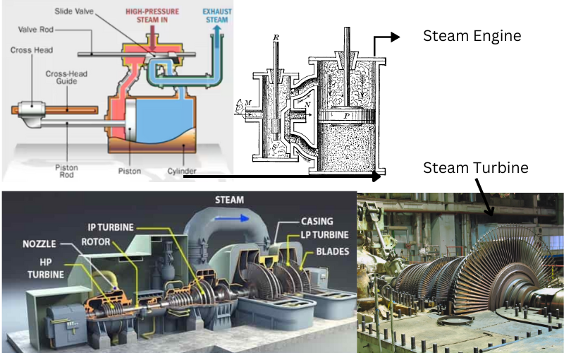
Prime mover steam engine or steam turbine of Thermal Power Plants:
A prime mover is a machine that converts thermal energy into mechanical energy. In a Thermal Power Plants, the prime mover is either.
1.Steam Engine: Uses the reciprocating motion of a piston to generate mechanical energy.
2.Steam Turbine: Uses the rotational motion of a turbine to generate mechanical energy.
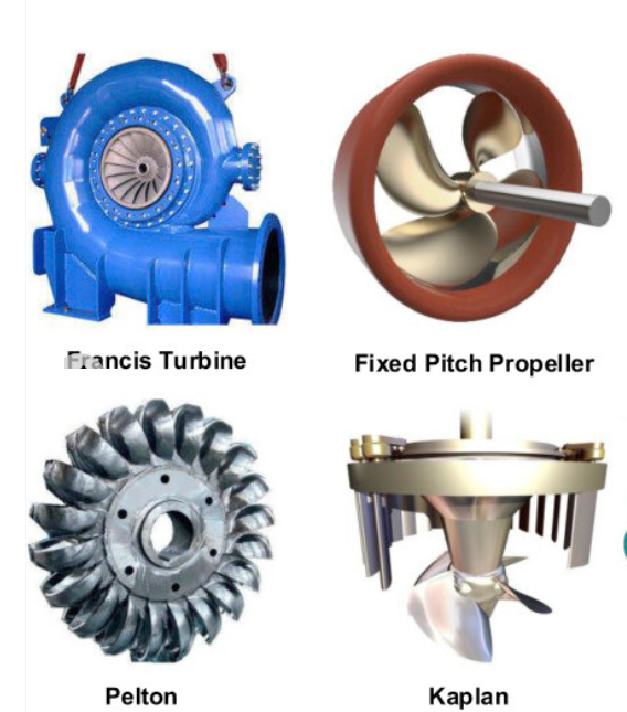
Types Of Turbines in Thermal Power Plants:
| Features | Steam Turbines | Water Turbines |
| Energy Source | Steam (from heated water) | Water (flowing or falling) |
| Operation Principle | Expands steam through turbine blades to generate mechanical energy | Utilizes water flow or pressure to turn turbine blades |
| Types | – Impulse Turbines: Uses steam jets (e.g., Pelton Wheel)- Reaction Turbines: Steam pressure acts on moving blades (e.g., Francis, Kaplan) | – Impulse Turbines: Water strikes turbine blades (e.g., Pelton Wheel)- Reaction Turbines: Water pressure acts on blades (e.g., Francis, Kaplan) |
| Applications | – Power generation in thermal and nuclear plants- Marine propulsion- Industrial processes | – Hydroelectric power generation- Water pumping- Irrigation |
| Efficiency | – Typically high, especially in high-pressure conditions- Efficiency increases with higher pressure and temperature | – Varies with flow conditions- Generally high in well-designed hydroelectric systems |
| Design Complexity | – Complex, especially in high-pressure, high-temperature applications- Requires sophisticated materials and design | – Generally simpler design compared to steam turbines- Easier maintenance and construction |
| Components | – Nozzles: Direct steam flow- Blades/Rotors: Convert steam energy to mechanical energy- Casing/Condenser: Encloses the turbine and condenses steam | – Runner Blades: Convert water energy to mechanical energy- Guide Vanes: Direct water flow to the blades- Draft Tube: Collects and directs water flow from the turbine |
| Typical Operating Conditions | – High temperature and pressure- Continuous high-energy input | – Varying flow rates and water heads- Continuous flow of water or fluctuating water levels |
| Maintenance | – Requires regular maintenance for high-pressure systems- Complex maintenance procedures | – Generally easier to maintain- Maintenance focused on water flow and blade condition |
| Startup Time | – Can be slower due to heating and pressurization- Requires careful ramp-up | – Typically faster start-up- Dependent on water availability and flow conditions |
| Environmental Impact | – Can produce greenhouse gases (if fossil fuels are used)- Waste heat management needed | – Generally low emissions- Environmental impact related to water flow and ecosystem disruption |
| Cost | – Higher initial cost due to complexity and materials- Potentially high operational and maintenance costs | – Lower initial cost- Generally lower operational and maintenance costs |
Condenser in Thermal Power Plants:
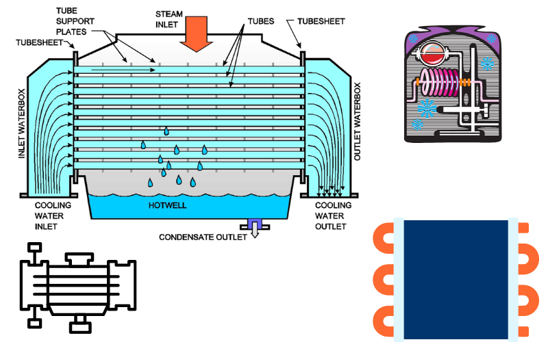
The condenser is a critical component in Thermal Power Plants responsible for condensing exhaust steam from the turbine into liquid water, allowing the cycle to repeat.
Function:
1.Condenses exhaust steam from the turbine into liquid water
2.Maintains a vacuum, which increases turbine efficiency
3.Allows the reuse of condensed water as feedwater
Types:
1.Surface Condenser: Most common type, uses a shell and tube design
2.Jet Condenser: Uses a jet of water to condense steam
3.Barometric Condenser: Uses atmospheric pressure to condense steam
Components:
1.Condenser Tubes: Where steam condenses into water
2.Water Boxes: Distribute cooling water to condenser tubes
3.Hotwell: Collects condensed water
4.Pumps: Circulate cooling water and condensed water
The condenser’s working principle is based on the following factors:
1.Temperature difference between steam and cooling water
2.Heat transfer rate
3.Flow rates of steam and cooling water
By condensing exhaust steam into liquid water, the condenser enables the reuse of water and maintains a stable vacuum, ensuring efficient operation of the Thermal Power Plants .The condenser works on the principle of heat transfer, where exhaust steam from the turbine is condensed into liquid water. The process occurs in the following steps:
1. Exhaust steam enters the condenser through inlet pipes.
2. Cooling water flows through the condenser tubes, absorbing heat from the steam.
3. As the steam loses heat, it condenses into liquid water, releasing its latent heat to the cooling water.
4. The condensed water collects in the hotwell, while the cooling water continues to flow through the tubes.
5. The cooled cooling water is pumped out of the condenser, while the condensed water is reused as feedwater.
The condenser maintains a vacuum, which helps to:
1.Increase turbine efficiency
2.Reduce steam pressure
3.Improve heat transfer
The condenser’s working principle is based on the following factors:
1.Temperature difference between steam and cooling water
2.Heat transfer rate
3.Flow rates of steam and cooling water
By condensing exhaust steam into liquid water, the condenser enables the reuse of water and maintains a stable vacuum, ensuring efficient operation of the Thermal Power Plants.
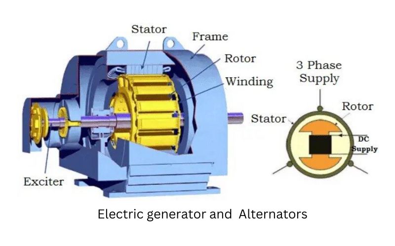
Electric generator and turbo alternator in Thermal power plants:
Electric Generator:
An electric generator is a machine that converts mechanical energy into electrical energy. It works on the principle of electromagnetic induction, where a magnetic field induces an electric current in a coil.
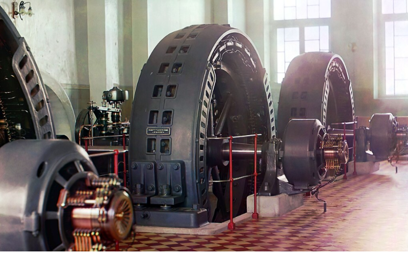
Turbo Alternator:
A turbo alternator is a type of electric generator that uses a turbine to drive the rotor. It’s commonly used in Thermal Power Plants to generate electricity on a large scale.
Components:
1.Rotor (moving part)
2.Stator (stationary part)
3.Magnetic field
4.Coils
5.Slip rings and brushes (for DC excitation)
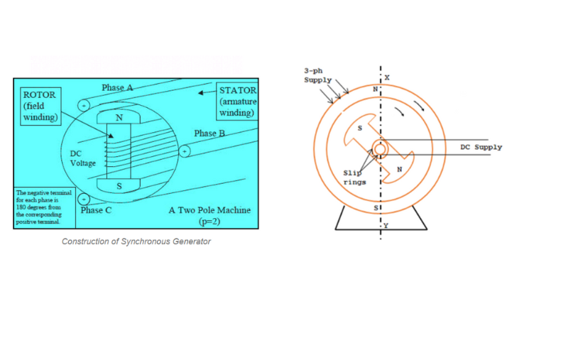
The construction of an alternator typically involves:
1) A rotor, which is the rotating part that generates a magnetic field when an electric current is passed through it.
2) A stator, which is the stationary part that contains windings that produce the electrical output as the rotor’s magnetic field passes through them.
3) A voltage regulator, which controls the output voltage of the alternator by adjusting the current flowing through the rotor. The interaction between the rotor’s magnetic field and the stator windings induces an alternating current (AC) in the stator, which is then converted to direct current (DC) for use in the vehicle’s electrical system.
1. Stator:
1.The stationary part of the alternator, consisting of a cylindrical frame and a set of copper windings (coils) embedded in slots.
2.The stator windings are typically connected in a three-phase configuration (star or delta).
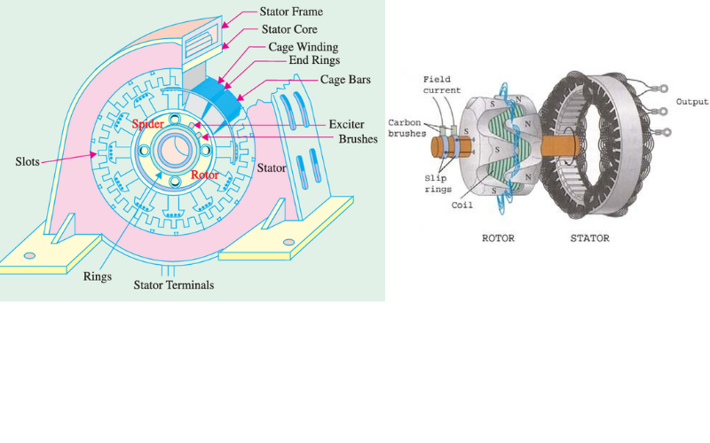
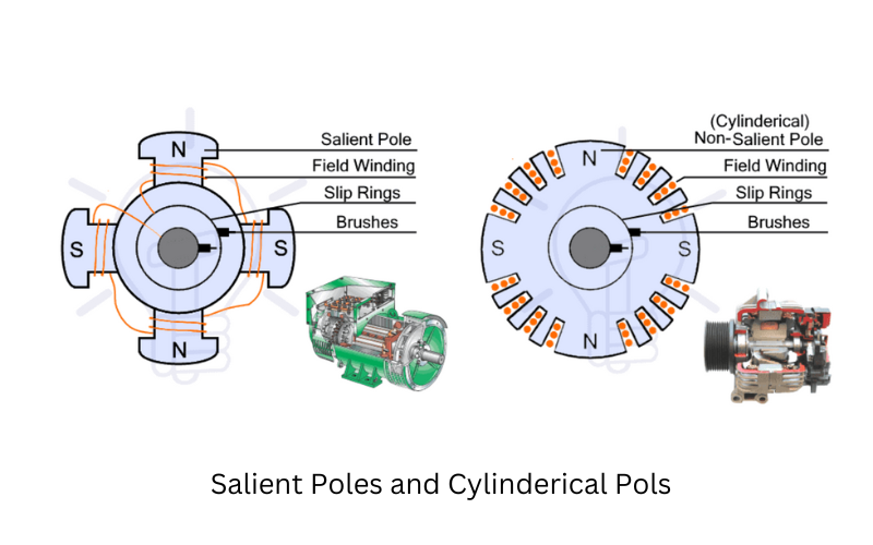
2. Rotor:
1.The rotating part of the alternator, consisting of a shaft and a magnetic field source (exciter).
2.The rotor can be either a
A)salient pole type (with projecting poles)
B)Cylindrical type Or Non salient pole type (with a smooth surface).
Working Principle:
1. Mechanical energy is input into the rotor, causing it to rotate.
2. The rotating rotor creates a magnetic field.
3. The magnetic field induces an electric current in the stator coils.
4. The current is collected and sent to the power grid.
EMF Generation Formula:
The EMF (Electromotive Force) generated in an alternator can be calculated using the following formula:
E = 4.44 x f x N x B x A
Where:
1.E = EMF generated (in volts)
2.f = Frequency of the AC output (in Hz)
3.N = Number of turns in the coil
4.B = Magnetic flux density (in teslas)
5.A = Cross-sectional area of the coil (in square meters)
Factors Affecting EMF Generation:
1. Frequency (f): Increasing frequency increases EMF.
2.Number of turns (N): Increasing turns increases EMF.
3.Magnetic flux density (B): Increasing flux density increases EMF.
4.Cross-sectional area (A): Increasing area increases EMF.
The formula “N = 120f/P” is used to calculate the synchronous speed (N) of a generator, where:
1.N = Synchronous speed in revolutions per minute (RPM)
2.f = Frequency of the generated voltage in Hertz (Hz) = 50 Hz
3.P = Number of poles in the generator
For a 50 Hz system, the formula becomes:
N = 120 x 50 / P
This formula means that for a given frequency (50 Hz) and number of poles (P), the generator will rotate at a specific speed (N) to produce the desired frequency.
Let’s calculate the synchronous speed for a few common pole configurations:
– 2 poles: N = 120 x 50 / 2 = 3000 RPM
– 4 poles: N = 120 x 50 / 4 = 1500 RPM
– 6 poles: N = 120 x 50 / 6 = 1000 RPM
In a 50 Hz system, these are the typical synchronous speeds for generators with 2, 4, or 6 poles. The generator will rotate at these speeds to produce the correct frequency for the grid.
Types of Alternators:
1.Synchronous alternators: Rotate at a fixed speed, generating a fixed frequency output.
2.Induction alternators: Rotate at a variable speed, generating a variable frequency output.
Applications:
1.Power plants: Generate electricity on a large scale.
2.Industrial power generation: Provide power for factories and industries.
3.Automotive: Used in vehicles to charge batteries and power accessories.
Fuel handling in Thermal Power Plants:
The main energy sources used to produce heat and steam in boilers are fossil fuels, specifically coal, fuel oil, and natural gas. Coal is the dominant energy source in many countries due to its abundance and widespread availability.Fuel handling in thermal power plants involves the processes of receiving, storing, and feeding fuel (such as coal, natural gas, or oil) into the plant’s boilers to generate steam and produce electricity. This critical system ensures a consistent and reliable supply of fuel to the power generation equipment, enabling the continuous operation of the Thermal Power Plants.
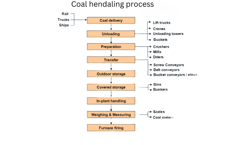
A Coal Handling Plant (CHP) is a vital component of a thermal power plant, ensuring efficient handling, storage, and delivery of coal to the boiler. CHP’s primary function is to supply coal to the boiler at the required rate and quality, enabling reliable and efficient power generation.
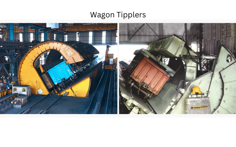
Coal delivery: Is received through rail, road, or ships and unloaded into storage facilities.
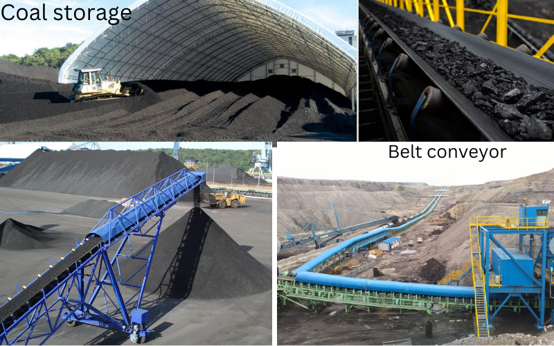
Storage coal: Coal is stored in silos, bunkers, or tanks to maintain a steady supply.
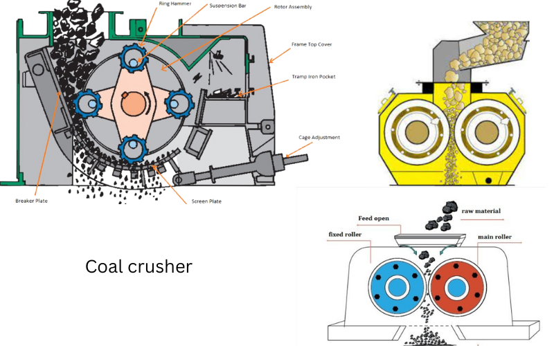
Preparation Coal: Coal is crushed and screened to ensure uniform size and quality. Coal is crushed to 10-20 mm size to improve combustion efficiency. Coal is screened to remove impurities and ensure uniform size.
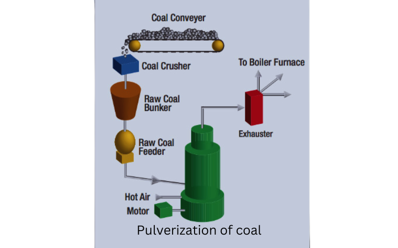
Transfer: Coal is transported to the boiler through conveyor belts, pipelines, or pneumatic systems.
Feeding: Coal is fed into the boiler through feeders or burners.
Ash Disposal in Thermal Power Plants:
In Thermal Power Plants , the management of combustion byproducts, specifically ash disposal, employs a range of methods. These processes are effectively illustrated with diagrams, showcasing the various techniques used to ensure efficient and environmentally responsible disposal.
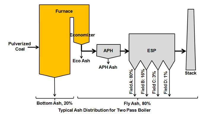
Ash Disposal Methods:
Dry Ash Handling:
In dry ash handling, ash is collected in hoppers and transported using conveyors or pneumatic systems to storage silos. This method minimizes water usage and is suitable for plants with limited water resources.
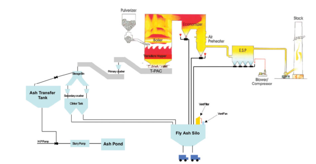
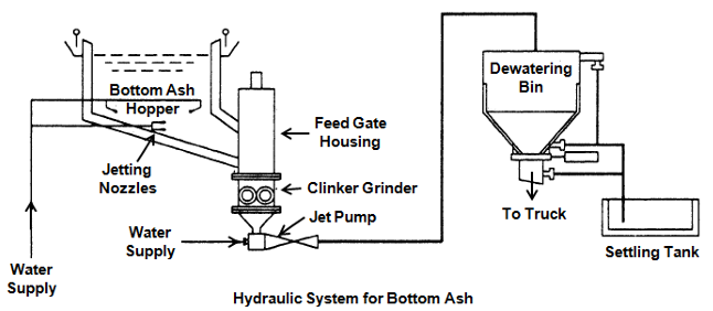
Wet Ash Handling:
Wet ash handling involves mixing ash with water to form a slurry, which is then pumped to ash ponds or lagoons. This method helps in controlling dust but requires significant water resources.
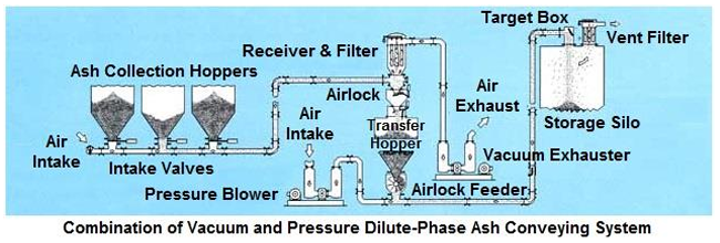
Pneumatic Ash Handling System:
This system uses a pneumatic conveying system to transport the ash to a storage silo. It’s commonly used in smaller Thermal Power Plants.
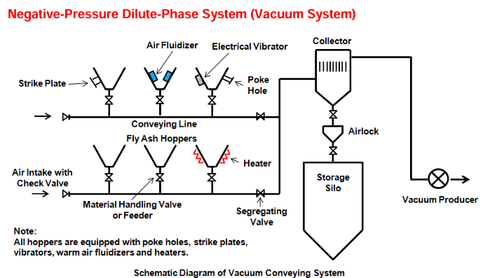
Vacuum Ash Handling System:
This system uses a vacuum conveying system to transport the ash to a storage silo. It’s often used in high-pressure boilers.
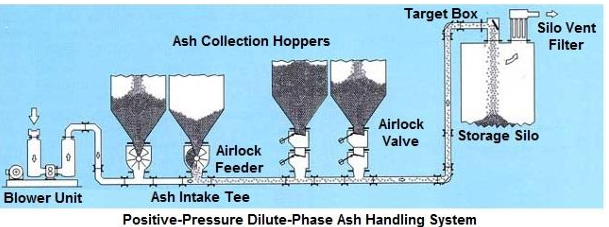
Pressure Pneumatic Ash Handling System:
This system uses a pressure pneumatic conveying system to transport the ash to a storage silo. It’s commonly used in larger Thermal Power Plants.
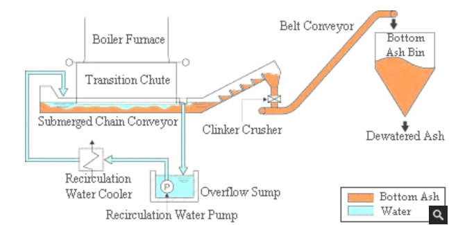
Submerged Scraper Conveyor (SSC) Ash Handling System:
This system uses a submerged scraper conveyor to transport the ash to a storage silo. It’s often used for bottom ash handling.
Dry Bottom Ash Handling System:
This system uses a dry bottom ash handling system to transport the ash to a storage silo. It’s commonly used for dry bottom ash handling.
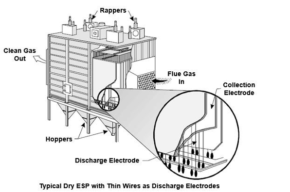
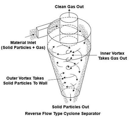
ESP (Electrostatic Precipitator): is a must have air pollution control device in many industries like Thermal Power Plants, cement factories and steel mills. Here’s an overview of ESP:
What is ESP?
ESP is a device that uses electrostatic charges to remove particulate matter (PM) like dust, ash and smoke from industrial exhaust gases.
How does ESP work?
The ESP process consists of the following steps:
1. Gas Flow: The exhaust gas from the industrial process enters the ESP.
2. Ionization: The gas passes through an ionization section where it is exposed to a high voltage electrostatic field and a corona discharge occurs which ionizes the gas molecules.
3. Particle Charging: The ionized gas molecules collide with the particulate matter and transfer electrostatic charge to the particles.
4. Precipitation: The charged particles are then attracted to a collection electrode where they are precipitated out of the gas stream.
5. Collection: The precipitated particles are collected in a hopper or collection bin.
Types of ESP
There are several types of ESP:
1. Dry ESP: Uses dry collection process where particles are collected in a hopper or collection bin.
2. Wet ESP: Uses wet collection process where particles are collected in a liquid bath.
3. Hybrid ESP: Combines features of dry and wet ESP.
Ash Recycling:
Ash recycling involves repurposing ash for various applications, such as in the construction industry for making bricks or cement. This method reduces the environmental impact and promotes sustainability
Dust handling systems:
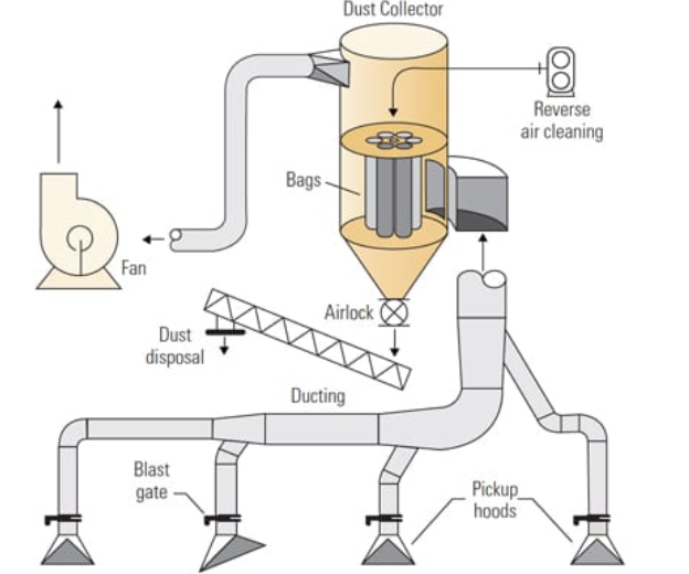
Dust collection collects fugitive dust that would otherwise escape from around equipment areas. Collected fugitive dust is fuel and should be delivered to the furnace and burned. Dust control systems come in many different area specific configurations. In the typical power plant they can be found between the coal unloading station and the outside stockpile, between the coal yard and the crusher station, between the crusher station and the tripper room, and near the coal storage bunker. A typical coal dust collection system has pickup hoods, ducting, branch lines, dust collector, fan and dust return system in Thermal Power Plants
Cooling Towers
Cooling towers serve as an essential element in Thermal Power Plants, significantly contributing to the dissipation of heat from the cooling systems.
Types of Cooling Towers
1. Natural Draft Cooling Towers: These structures rely on natural convection for heat dissipation, functioning without mechanical aids Thermal Power Plants.
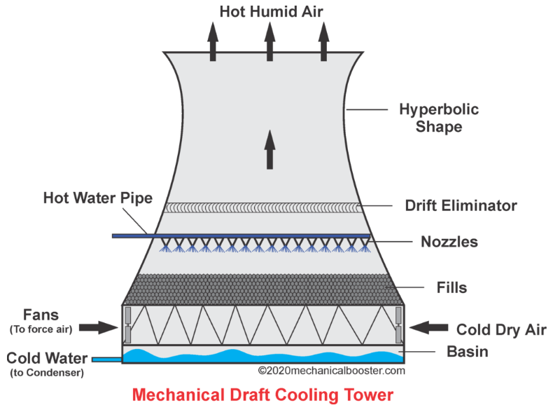
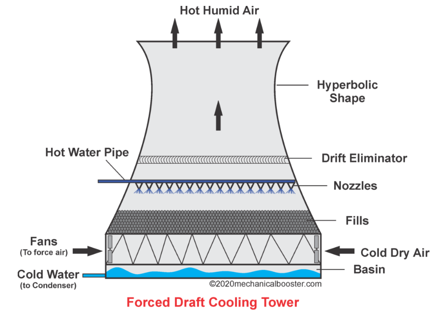
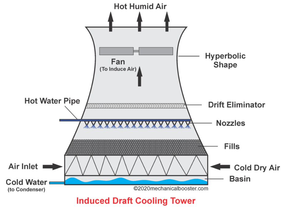
2. Mechanical Draft Cooling Towers: These systems employ fans or blowers to actively circulate air through the tower, thereby improving heat exchange efficiency.
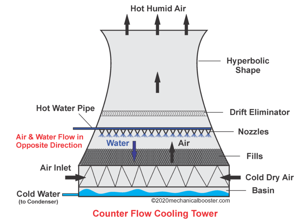
3. Hybrid Cooling Towers: These designs integrate both natural and mechanical draft methods to optimize performance.
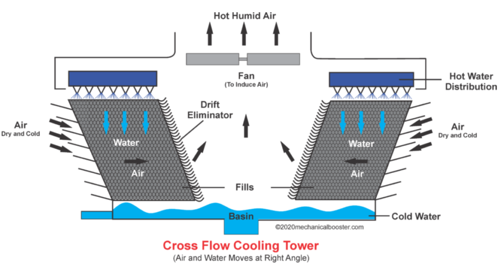
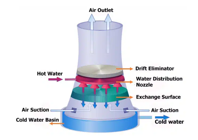
Components of Cooling Towers
1. Tower Structure: The external framework of the tower, commonly constructed from materials such as concrete, steel, or fiberglass.
2. Fill Pack: An internal lattice structure where the heat exchange between water and air takes place.
3. Spray Nozzles: Devices that ensure uniform distribution of water across the fill pack.
4. Fans or Blowers: Mechanical elements that facilitate increased airflow within the tower.
5. Drift Eliminators: Mechanisms designed to reduce water loss caused by drift.
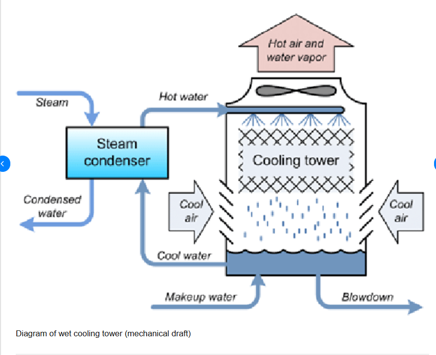
Working Principle of Cooling Towers
1. Heat Transfer: Heated water from the cooling system of the power plant is pumped to the top of the cooling tower.
2. Water Distribution: The water is evenly spread throughout the fill pack via spray nozzles.
3. Air Flow: Air is drawn through the tower, either by natural means or mechanical assistance, allowing it to interact with the water.
4. Evaporative Cooling: As air passes through the tower, it induces evaporation of a portion of the water, effectively removing heat from the system.
5. Cool Water: The cooled water is collected at the base of the tower and is then recirculated back into the power plant’s cooling system.
Cooling towers in power plants play a crucial role in increasing the efficiency of the power plant by providing cooled water, known as condenser cooling water, which is then used as feedwater in boilers.
1. Condenser Cooling Water: The cooling tower cools the condenser cooling water, which is used to condense the steam coming out of the turbine.
2. Feedwater: The cooled condenser cooling water is then used as feedwater in the boiler.
3. Increased Efficiency: By using cooled feedwater, the boiler’s efficiency is increased, as it requires less energy to heat the water to produce steam.
4. Improved Power Generation: The increased efficiency of the boiler translates to improved power generation, as more electricity can be produced from the same amount of fuel.
The use of cooling towers to provide cooled feedwater is a common practice in many power plants, including:
1. Fossil-fuel power plants: Cooling towers are widely used in fossil-fuel power plants, such as coal, natural gas, and oil-fired power plants.
2. Nuclear power plants: Cooling towers are also used in nuclear power plants to provide cooled feedwater for the reactor.
Overall, the use of cooling towers to provide cooled feedwater is an important aspect of power plant operation, as it helps to increase efficiency, reduce fuel consumption, and improve power generation.
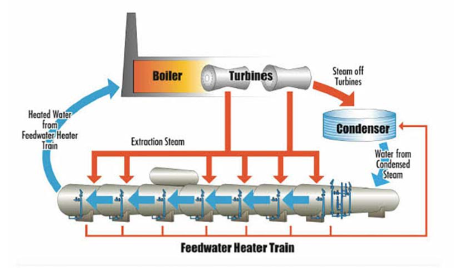
Feedwater heaters
Feedwater heaters are heat exchangers that preheat the feedwater (water used to produce steam) before it enters the boiler. This process increases the temperature of the feedwater, reducing the amount of heat energy required to produce steam in Thermal Power Plants.
Types of Feedwater Heaters:
1. Low-Pressure Feedwater Heaters (LPFWH): These heaters are located in the low-pressure steam system and typically operate at pressures below 100 psig (689 kPa).
2. High-Pressure Feedwater Heaters (HPFWH): These heaters are located in the high-pressure steam system and typically operate at pressures above 100 psig (689 kPa).
3. Deaerating Feedwater Heaters: These heaters not only preheat the feedwater but also remove dissolved gases, such as oxygen and carbon dioxide.
Working Principle:
1. Feedwater Supply: Feedwater from the condenser or deaerator is supplied to the feedwater heater.
2. Steam Extraction: Steam is extracted from the turbine or boiler and directed to the feedwater heater.
3. Heat Transfer: The extracted steam transfers its heat energy to the feedwater, increasing its temperature.
4. Preheated Feedwater: The preheated feedwater is then directed to the boiler, where it is converted into steam.
Advantages:
1. Improved Efficiency: Feedwater heaters increase the overall efficiency of the Thermal Power Plants by reducing the amount of heat energy required to produce steam.
2. Reduced Fuel Consumption: By preheating the feedwater, less fuel is required to produce the same amount of steam.
3. Increased Power Output: Feedwater heaters enable power plants to generate more electricity from the same amount of fuel.
Challenges and Limitations:
1. Corrosion: Feedwater heaters can be susceptible to corrosion, which can reduce their efficiency and lifespan.
2. Fouling: Deposits and fouling can occur on the heat transfer surfaces, reducing the effectiveness of the feedwater heater.
3. Maintenance: Regular maintenance is essential to ensure the optimal performance of feedwater heaters.
In summary, feedwater heaters play a vital role in improving the efficiency and reducing the fuel consumption of Thermal Power Plants. By preheating the feedwater, these heaters enable power plants to generate more electricity while minimizing their environmental impact.
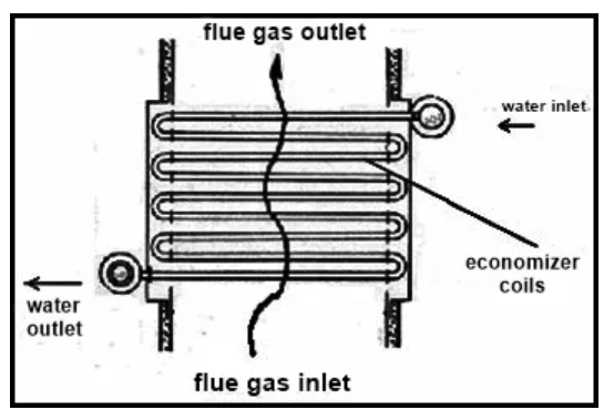
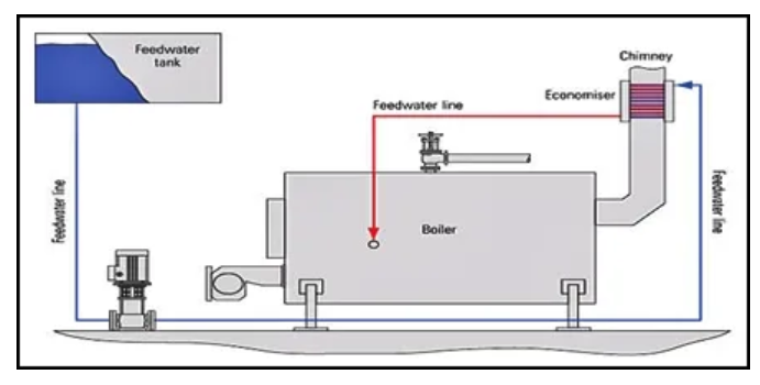
Economizers
An economizer is a heat exchanger that uses the heat from the flue gas to preheat the boiler feedwater. This process increases the temperature of the feedwater, reducing the amount of heat energy required to produce steam.
Types of Economizers
1. Convective Economizers: These economizers use the convective heat transfer principle to preheat the feedwater.
2. Radiative Economizers: These economizers use the radiative heat transfer principle to preheat the feedwater.
3. Combination Economizers: These economizers use a combination of convective and radiative heat transfer principles to preheat the feedwater.
Working Principle
1. Flue Gas Supply: The flue gas from the boiler is directed to the economizer.
2. Feedwater Supply: The boiler feedwater is supplied to the economizer.
3. Heat Transfer: The heat from the flue gas is transferred to the feedwater, increasing its temperature.
4. Preheated Feedwater: The preheated feedwater is then directed to the boiler, where it is converted into steam.
Advantages
1. Improved Efficiency: Economizers improve the overall efficiency of the power plant by reducing the amount of heat energy required to produce steam.
2. Reduced Fuel Consumption: By preheating the feedwater, economizers reduce the amount of fuel required to produce the same amount of steam.
3. Increased Power Output: Economizers enable Thermal Power Plants to generate more electricity from the same amount of fuel.
Challenges and Limitations
1. Corrosion: Economizers can be susceptible to corrosion, which can reduce their efficiency and lifespan.
2. Fouling: Deposits and fouling can occur on the heat transfer surfaces, reducing the effectiveness of the economizer.
3. Maintenance: Regular maintenance is essential to ensure the optimal performance of economizers.
Conclusion
Economizers play a vital role in improving the efficiency and reducing the fuel consumption of power plants. By preheating the boiler feedwater, economizers enable Thermal Power Plants to generate more electricity while minimizing their environmental impact.
Superheaters
A superheater is a heat exchanger that heats the saturated steam produced in the boiler to a higher temperature, making it superheated steam.
Types of Superheaters
1. Convection Superheaters: These superheaters use the convective heat transfer principle to heat the steam.
2. Radiation Superheaters: These superheaters use the radiative heat transfer principle to heat the steam.
3. Combination Superheaters: These superheaters use a combination of convective and radiative heat transfer principles to heat the steam.
Working Principle
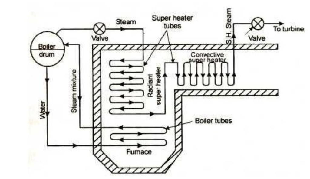
1. Saturated Steam Supply: The saturated steam produced in the boiler is directed to the superheater.
2. Heat Transfer: The heat from the flue gas is transferred to the saturated steam, increasing its temperature and making it superheated steam.
3. Superheated Steam: The superheated steam is then directed to the turbine, where it expands and produces work.
Advantages
1. Increased Efficiency: Superheaters increase the overall efficiency of the Thermal Power Plants by allowing the turbine to operate at higher temperatures and pressures.
2. Increased Power Output: Superheaters enable Thermal Power Plants to generate more electricity from the same amount of fuel.
3. Reduced Fuel Consumption: By increasing the efficiency of the Thermal Power Plants, superheaters reduce the amount of fuel required to produce the same amount of electricity.
Challenges and Limitations
1. Corrosion: Superheaters can be susceptible to corrosion, which can reduce their efficiency and lifespan.
2. Fouling: Deposits and fouling can occur on the heat transfer surfaces, reducing the effectiveness of the superheater.
3. Maintenance: Regular maintenance is essential to ensure the optimal performance of superheaters.
Conclusion
Superheaters play a vital role in increasing the efficiency and power output of Thermal Power Plants. By heating the saturated steam to a higher temperature, superheaters enable power plants to generate more electricity while minimizing their environmental impact.
Air preheaters
An air preheater is a heat exchanger that uses the heat from the flue gas to preheat the combustion air before it enters the boiler.
Types of Air Preheaters
1. Recuperative Air Preheaters: These preheaters use a heat exchanger to transfer heat from the flue gas to the combustion air.
2. Regenerative Air Preheaters: These preheaters use a rotating heat exchanger to transfer heat from the flue gas to the combustion air.
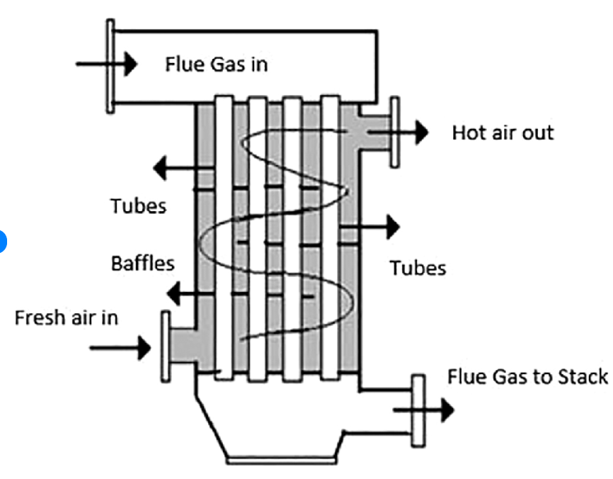
Working Principle
1. Flue Gas Supply: The flue gas from the boiler is directed to the air preheater.
2. Combustion Air Supply: The combustion air is directed to the air preheater.
3. Heat Transfer: The heat from the flue gas is transferred to the combustion air, increasing its temperature.
4. Preheated Air: The preheated air is then directed to the boiler, where it is used for combustion.
Advantages
1. Improved Efficiency: Air preheaters improve the overall efficiency of the Thermal Power Plants by reducing the amount of heat energy required for combustion.
2. Reduced Fuel Consumption: By preheating the combustion air, air preheaters reduce the amount of fuel required to produce the same amount of steam.
3. Increased Power Output: Air preheaters enable Thermal Power Plants to generate more electricity from the same amount of fuel.
Challenges and Limitations
1. Corrosion: Air preheaters can be susceptible to corrosion, which can reduce their efficiency and lifespan.
2. Fouling: Deposits and fouling can occur on the heat transfer surfaces, reducing the effectiveness of the air preheater.
3. Maintenance: Regular maintenance is essential to ensure the optimal performance of air preheaters.
Conclusion
Air preheaters play a vital role in improving the efficiency and reducing the fuel consumption of Thermal Power Plants. By preheating the combustion air, air preheaters enable power plants to generate more electricity while minimizing their environmental impact.
Here are the facts about Thermal Power Plants in a Q&A.
What is the primary purpose of a thermal power plant?
Answer: To convert heat energy into electrical energy.
What is the main fuel used in thermal power plants?
Answer: Coal
What is the Rankine cycle?
Answer: A thermodynamic cycle used to convert heat energy into mechanical energy.
What are the four stages of the Rankine cycle?
Answer: Isentropic compression, constant pressure heat addition, isentropic expansion, and constant pressure heat rejection.
What is the purpose of a boiler in a thermal power plant?
Answer: To generate high-pressure steam from water.
What are the two main types of boilers?
Answer: Fire tube boilers and water tube boilers.
What is the purpose of an economizer?
Answer: To preheat the boiler feedwater using the heat from the flue gas.
What is the purpose of a superheater?
Answer: To heat the saturated steam produced in the boiler to a higher temperature.
What is the purpose of an air preheater?
Answer: To preheat the combustion air before it enters the boiler.
What is the purpose of a condenser in a thermal power plant?
Answer: To condense the exhaust steam from the turbine into liquid water.
What is the purpose of a cooling tower?
Answer: To dissipate heat from the cooling system.
What is the purpose of a feedwater heater?
Answer: To preheat the boiler feedwater using the heat from the steam.